zibbit u2
Well-Known Member
- Joined
- Jan 25, 2015
- Messages
- 465
- Location
- Victoria BC Canada
Ok, since a few of us with older Hyperstrada 821's will be coming up for a timing belt change soon, I figured I'd show a few photos and post a few quick tips about doing the belt change yourself.
I will state a disclaimer, I am NOT a Ducati or Motorcycle trained mechanic. By that, I am not responsible for actions you undertake on your bike. My mechanical background includes being a certified aircraft mechanic trained by the the Airforce. This write up is intended to be guide to supplement the official Ducati service manual. It is in NO WAY intended to replace the manual.
Ok, with that out of the way, the reason why I changed my belts at approximately the 1/2 life cycle mark because they were loose enough to justify the change. When I checked the tension acoustically with both belts at TDC they were showing aprox 71-73 Hz. Ducati has set the limit for used belts at 70 Hz, normal operating "reclaimed" used belts @ 80 Hz, and new belts at 110 Hz. So, for the sake of $160 to change them out, I figured this was a justifiable means to protect the motor. Kinda along the same lines of spending the extra cash during oil changes to install new crush washers on all of the oil drain plugs..
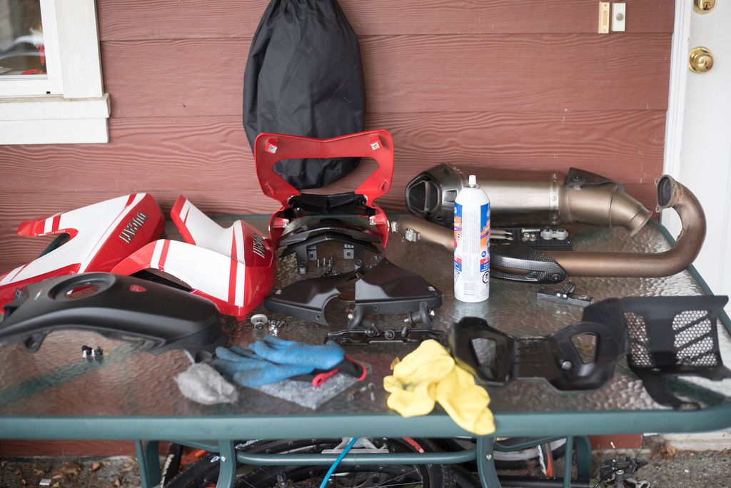
So following the manual remove the Seat, Gas Tank, Horizontal Cylinder Primary Exhaust, Timing Belt Covers and both Spark Plugs. You should end up with a pile of parts that look similar to this;
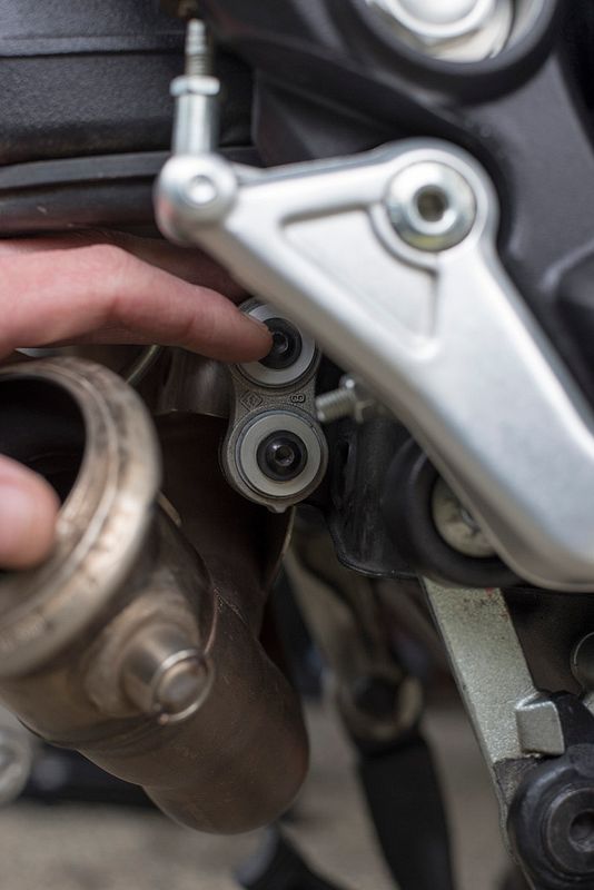
A note about removing the Horizontal Cylinder Exhaust Pipe: To get the pipe to separate from the collector pipe, I had to removed the silencer assembly, 3 header pipe nuts (on the cylinder head), 2 heat shield screws (near the shock), both collector springs and the lower collector mount shown below. Once all the screws were removed from the heatsheild pay note because there will be two thick washers underneath that will go bouncing across the floor. They're sandwiched between the pipe and the shield. Once all of those were removed you can wiggle both the collector pipe and the horizontal pipe to get them to separate.
A note about lifting the tank out of the frame: To get the rear of the tank to lift out, you'll need to remove all 3 screws holding the RH subframe lower fairing in place because the seat release latch assembly prevents anything from lifting.

Now, if you don't have the proper crank rotating tool to align the timing marks. You can easily to it this way... on the center timing (timing layshaft) pulley you'll see two threaded holes that you can fit a couple M6x1.0x40 bolts into. With the SPARK PLUGS REMOVED!!!, you can easily rotate the motor. There will be a little resistance to get it rotating, but it should be nothing significant. Normal direction of rotation is Counter Clockwise.
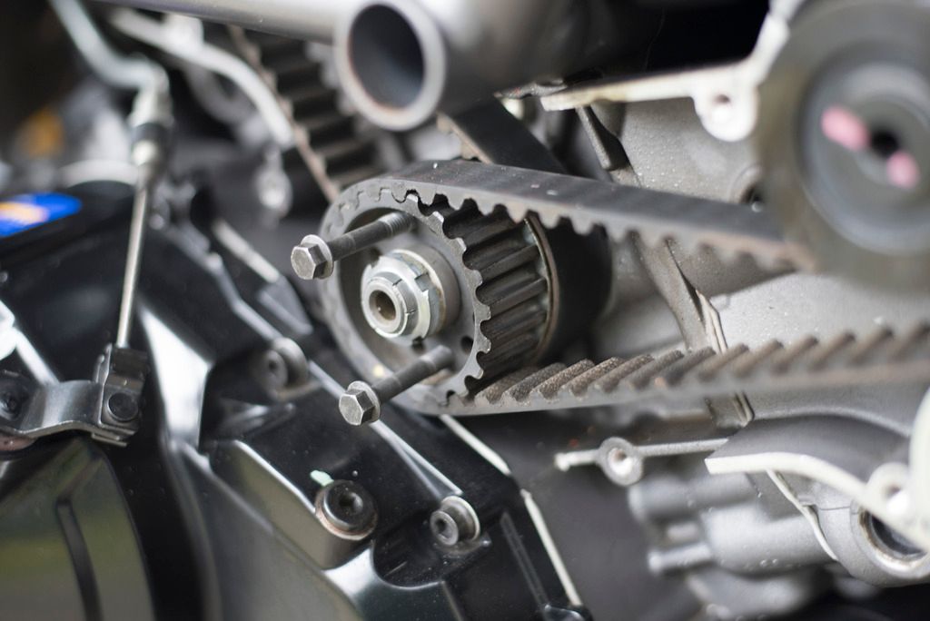
Now rotate the motor to align the dot of the "crank" pulley with the notch in the RH case. You'll be left with a motor looking like this;

The next closeups were taken with the Timing mark aligned for the "crank" Layshaft.
Closeup of the layshaft alignment mark:

Closeup of the horizontal cylinder camshafts:
NOTE the alignment of the notches on the end of the camshafts, relative to the cylinder head.
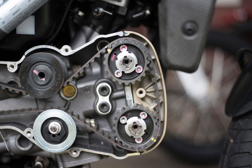
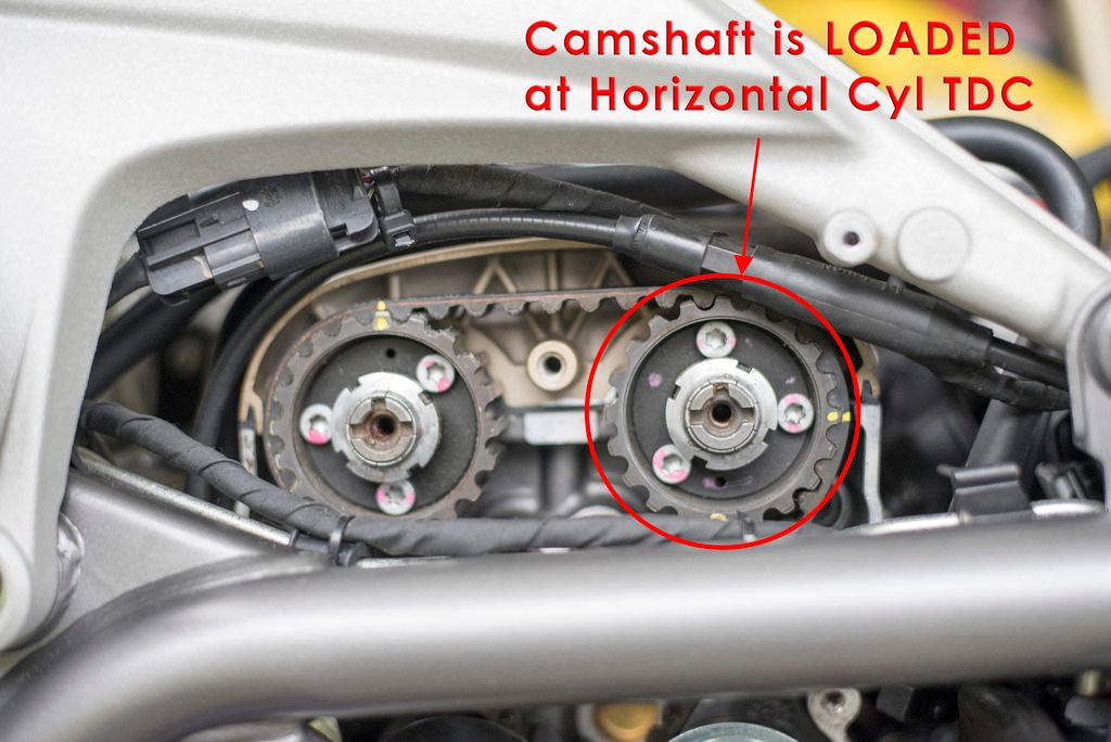
Closeup of the vertical cylinder camshaft:
NOTE: The intake camshaft is loaded, because this cylinder is NOT at TDC. Which makes it a bitch to remove and install the belt without the special tool. Also note, that as per the horizontal cylinder, both camshaft notches line up as well.
Now, as per all the other instructions online, you mark easily identifiable points along the timing system and transcribe those to the new belts. Also note the direction of travel and if it is a Horizontal or Vertical belt. As per the closeups, I chose to mark where the factory "yellow dots" were relative to belt system. Only caveat, was the loaded intake camshaft on the vertical cylinder, I added my own dot because the factory "yellow dot" is at approximately the 6 o'clock position.
Below is a picture of the critical tooth count that you MUST maintain on the Idler pulley (non-adjustable) side of the belt. Same goes for the vertical cylinder, you must keep the belt teeth the same on the Idler pulley side of the belt.

Once you've got the new belts into place, you can start tensioning the horizontal timing belt to 110 Hz +/- 5%. Apply a little tension on the vertical cylinder belt, then rotate the layshaft approximately 90 degrees to get the vertical cylinder at TDC. Easy way you can visually verify you're at TDC is with a "screwdriver method" in the spark plug hole. Now tension the vertical belt to 110 Hz +/- 5%. I found that with both belts tensioned they were showing about 1 cm of total deflection dead center between the widest pulleys with the respective cylinder at TDC (where you "strummed" the belt).
Once both belts are tensioned, rotate the motor a few times and verify all the camshafts "notches" return to the original configuration before you removed the belts with the Timing mark aligned. Also re-check the tension of both belts in their respective TDC configuration.
Now put it all back together. Good luck with those washers on the heat-shield.. haha
I will state a disclaimer, I am NOT a Ducati or Motorcycle trained mechanic. By that, I am not responsible for actions you undertake on your bike. My mechanical background includes being a certified aircraft mechanic trained by the the Airforce. This write up is intended to be guide to supplement the official Ducati service manual. It is in NO WAY intended to replace the manual.
Ok, with that out of the way, the reason why I changed my belts at approximately the 1/2 life cycle mark because they were loose enough to justify the change. When I checked the tension acoustically with both belts at TDC they were showing aprox 71-73 Hz. Ducati has set the limit for used belts at 70 Hz, normal operating "reclaimed" used belts @ 80 Hz, and new belts at 110 Hz. So, for the sake of $160 to change them out, I figured this was a justifiable means to protect the motor. Kinda along the same lines of spending the extra cash during oil changes to install new crush washers on all of the oil drain plugs..
So following the manual remove the Seat, Gas Tank, Horizontal Cylinder Primary Exhaust, Timing Belt Covers and both Spark Plugs. You should end up with a pile of parts that look similar to this;

A note about removing the Horizontal Cylinder Exhaust Pipe: To get the pipe to separate from the collector pipe, I had to removed the silencer assembly, 3 header pipe nuts (on the cylinder head), 2 heat shield screws (near the shock), both collector springs and the lower collector mount shown below. Once all the screws were removed from the heatsheild pay note because there will be two thick washers underneath that will go bouncing across the floor. They're sandwiched between the pipe and the shield. Once all of those were removed you can wiggle both the collector pipe and the horizontal pipe to get them to separate.

A note about lifting the tank out of the frame: To get the rear of the tank to lift out, you'll need to remove all 3 screws holding the RH subframe lower fairing in place because the seat release latch assembly prevents anything from lifting.

Now, if you don't have the proper crank rotating tool to align the timing marks. You can easily to it this way... on the center timing (timing layshaft) pulley you'll see two threaded holes that you can fit a couple M6x1.0x40 bolts into. With the SPARK PLUGS REMOVED!!!, you can easily rotate the motor. There will be a little resistance to get it rotating, but it should be nothing significant. Normal direction of rotation is Counter Clockwise.

Now rotate the motor to align the dot of the "crank" pulley with the notch in the RH case. You'll be left with a motor looking like this;

The next closeups were taken with the Timing mark aligned for the "crank" Layshaft.
Closeup of the layshaft alignment mark:

Closeup of the horizontal cylinder camshafts:
NOTE the alignment of the notches on the end of the camshafts, relative to the cylinder head.

Closeup of the vertical cylinder camshaft:
NOTE: The intake camshaft is loaded, because this cylinder is NOT at TDC. Which makes it a bitch to remove and install the belt without the special tool. Also note, that as per the horizontal cylinder, both camshaft notches line up as well.

Now, as per all the other instructions online, you mark easily identifiable points along the timing system and transcribe those to the new belts. Also note the direction of travel and if it is a Horizontal or Vertical belt. As per the closeups, I chose to mark where the factory "yellow dots" were relative to belt system. Only caveat, was the loaded intake camshaft on the vertical cylinder, I added my own dot because the factory "yellow dot" is at approximately the 6 o'clock position.
Below is a picture of the critical tooth count that you MUST maintain on the Idler pulley (non-adjustable) side of the belt. Same goes for the vertical cylinder, you must keep the belt teeth the same on the Idler pulley side of the belt.

Once you've got the new belts into place, you can start tensioning the horizontal timing belt to 110 Hz +/- 5%. Apply a little tension on the vertical cylinder belt, then rotate the layshaft approximately 90 degrees to get the vertical cylinder at TDC. Easy way you can visually verify you're at TDC is with a "screwdriver method" in the spark plug hole. Now tension the vertical belt to 110 Hz +/- 5%. I found that with both belts tensioned they were showing about 1 cm of total deflection dead center between the widest pulleys with the respective cylinder at TDC (where you "strummed" the belt).
Once both belts are tensioned, rotate the motor a few times and verify all the camshafts "notches" return to the original configuration before you removed the belts with the Timing mark aligned. Also re-check the tension of both belts in their respective TDC configuration.
Now put it all back together. Good luck with those washers on the heat-shield.. haha
Last edited:
